What is a Jablonski Diagram (Perrin-Jablonski Diagram)?
The Jablonski diagram is widely used in fluorescence spectroscopy to illustrate the excited states of a molecule and the radiative and non-radiative transitions that can occur between them.
History of the Jablonski Diagram
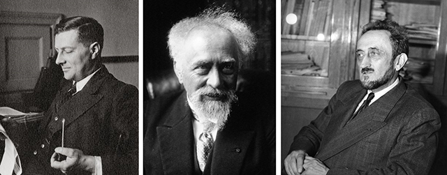
The Jablonski Diagram is named after Polish physicist Aleksander Jabłoński who, due to his many pioneering contributions, is regarded as the father of fluorescence spectroscopy.1 He received his doctorate for the work “On the influence of the change of wavelengths of excitation light on the fluorescence spectra” where he provided experimental proof that the fluorescence spectrum is independent to the wavelength of the excitation light. Some of his most notable contributions to fluorescence spectroscopy were furthering the understanding of the theory of fluorescence polarisation in solutions; the concept of concentration quenching; and the development of the famous diagram which now bears his name to explain the spectra and kinetics of fluorescence, delayed fluorescence and phosphorescence.1
Figure 1: 1 Aleksander Jabłoński (left), 1898-1980, Jean Baptiste Perrin (centre), 1870-1942, and Francis Perrin (right), 1901-1992. Images are in the public domain.
However, the diagram is more correctly called a Perrin-Jablonski diagram to recognise the important contributions in its development by French physicists Jean Baptist Perrin, winner of the 1926 Nobel Prize in Physics, and his son Francis Perrin who both contributed greatly to the theory of fluorescence in the 1920s and 1930s.2,3 Jean Perrin introduced the concept of resonant energy transfer between molecules and developed a theory to explain thermally activated delayed fluorescence.3 Francis Perrin arguably made an even larger impact to fluorescence theory than his father, by developing the active sphere model for quenching, establishing the relationship between fluorescence quantum yield and lifetime and the theory for fluorescence polarisation.3
Jean Perrin was likely the first person to use a molecular energy level diagram to illustrate the absorption and emission of light, which he used to explain the concept of thermally activated delayed fluorescence by introducing a ‘metastable state’.4 This model and diagram was then explained in greater detail in Francis Perrin’s doctoral thesis.4 The key contribution of Jabłoński to the development of the diagram was allowing a radiative transition from the metastable state back to the ground state, resulting in a second emission pathway that occurs at longer wavelength (phosphorescence). The final development was the work by A. Terenin, G. N. Lewis and M. Kasha who established that the metastable state was, in fact, the triplet state.4 The modern diagram could, therefore, be most accurately called a Perrin-Jablonski diagram modified by Terenin, Lewis and Kasha.
How to Interpret a Jablonski Diagram
The Jablonski diagram is a powerful tool for visualising the possible transitions that can occur after a molecule has been photoexcited. A typical Jablonski diagram is shown in Figure 2 and the key components and transitions that make up the diagram are explained below.
Energy Levels
The energy levels of a molecule are shown by the horizontal black lines; with energy increasing along the vertical axis of the diagram. The bold lines represent the lowest vibrational level of each electronic state, with the higher vibrational levels represented by thinner lines. The vibrational levels become more closely spaced as energy increases and eventually form a continuum; for clarity, only a subset of these vibrational levels are represented on the diagram.
The naming of the electronic states is based on the spin angular momentum configuration of each state. Singlet states (a total spin angular momentum of zero) are denoted by an S and triplet states (a total spin angular momentum of one) by T:
S0 is the singlet ground state of the molecule
S1 is the first excited singlet state and Sn is the nth excited singlet state
T1 is the first excited triplet state and Tn is the nth excited triplet state
Radiative & Non-Radiative Transitions
The coloured arrows represent the various transitions that can transfer energy between the molecular states and are split into radiative and non-radiative transitions.
Radiative transitions are transitions between two molecular states where the energy difference is emitted or absorbed by photons and are represented in a Jablonski diagram by straight arrows.
Non-radiative transitions are transitions between two molecular states without the absorption or emission of photons and are represented in a Jablonski diagram by undulating arrows.

Figure 2: A typical Jablonski diagram showing the possible radiative and non-radiative transitions.
Absorption
A radiative transition from a lower to a higher electronic state of a molecule. The energy of the photon is converted to the internal energy of the molecule.
A molecule is promoted from its ground state to a higher state by absorption of a photon which is represented by the blue arrows in Figure 2. It is the fastest transition in the Jablonski diagram, occurring on a timescale of order 10-15 s. At room temperature, the majority of molecules in a population will be in the lowest vibrational level of the ground state (Boltzmann distribution) and absorption is therefore shown to start from this level. Absorption of a photon promotes the molecule from the S0 to one of the vibrational levels of the singlet excited states (S1, S2,…). Direct excitation to the triplet excited states (T1, T2,…) is not possible due to conservation of angular momentum.
Vibrational Relaxation
A non-radiative transition to a lower vibrational level within the same electronic state.
After a molecule has been promoted to an excited state by absorption, it is in a non‑equilibrium state and will eventually dissipate the energy that it has gained and return to the ground state. The first way that energy is lost is through vibrational relaxation (orange arrows); where excess vibrational energy is lost to vibrational modes within either the same molecule (intramolecular) or to surrounding molecules (intermolecular) until the lowest vibrational level of the electronic state is reached. Vibrational relaxation occurs on a rapid time-scale of 10-12 – 10-10 s and outcompetes all other transitions.
Internal Conversion
A non-radiative transition between two electronic states of the same spin multiplicity.
A molecule in a higher lying singlet electronic state may also undergo internal conversion to a lower lying singlet electronic state which is shown by the purple arrows in Figure 2. Internal conversion is immediately followed by vibrational relaxation to the lowest vibrational level of the electronic state.
The rate of internal conversion is inversely proportional to the energy gap between the two electronic states. Internal conversion of the closely spaced higher lying singlet excited states (S3 → S2, S2 → S1 etc.) will proceed rapidly on a timescale of 10-11 to 10-9 s. In contrast, the energy gap between the S1 and the S0 is much wider and internal conversion between these states occurs on a slower timescale and will be in competition with other transitions such as fluorescence and intersystem crossing.
Fluorescence
A radiative transition between two electronic states of the same spin multiplicity.
The emission of photons from the S1 → S0 radiative transition is known as fluorescence which occurs on a timescale of 10-10 to 10-7 s and is shown by the green arrows in Figure 2. As a consequence of the rapid vibrational relaxation and internal conversion processes described above the fluorescence occurs, with some exceptions, from the lowest vibrational level of the first electronic excited singlet state to the singlet ground state. This energy loss prior to fluorescence is the physical origin of the famous Kasha’s Rule which states that: “luminescence (fluorescence or phosphorescence) only occurs with appreciable yield from the lowest excited state of a given multiplicity”.5 It is also responsible for the Stokes-Shift; where the fluorescence occurs at a longer wavelength than the absorption.
Intersystem Crossing
A non-radiative transition between two isoenergetic vibrational levels belonging to electronic states of different spin multiplicity.
An alternative transition to fluorescence and internal conversion is intersystem crossing from the S1 to the T1 state which is shown by the aqua coloured arrows in Figure 2. This transition is in principle forbidden due to conservation of spin angular momentum; however, spin-orbit coupling between the spin angular momentum and the orbital angular momentum makes it weakly allowed. Intersystem crossing is in competition with the other S1 depopulation transitions (internal conversion and fluorescence) and is too slow to be relevant for the majority of purely organic molecules. One method of increasing the intersystem crossing rate is the incorporation of heavy atoms into the molecule which increases the spin-orbit coupling strength. After intersystem crossing the molecule will immediately undergo vibrational relaxation to the ground vibrational level of T1.
Phosphorescence
A radiative transition between two electronic states of different spin multiplicity.
The emission of photons from the T1 → S0 transition is known as phosphorescence. Similarly to intersystem crossing; phosphorescence is in principle a forbidden transition but is weakly allowed through spin-orbit coupling. A consequence of being a forbidden transition is that the phosphorescence rate constant is very low and phosphorescence therefore occurs on a much longer timescale than fluorescence, with typical phosphorescence lifetimes being in the 10-6 to 10 s range.
Delayed Fluorescence
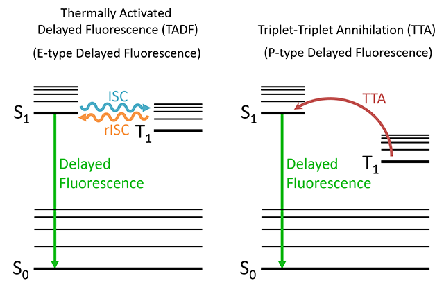
A third type of radiative transition known as delayed fluorescence, which is not typically shown in the standard Jablonski diagram of Figure 2, is also possible. Delayed fluorescence occurs when a molecule in the T1 state transitions to the S1 state followed by a radiative transition to the S0; which results in an emission identical in wavelength to standard fluorescence but occurring on a longer timescale. Delayed fluorescence occurs through two distinct mechanisms which are explained below.
Thermally Activated Delayed Fluorescence (E-type Delayed Fluorescence)
In thermally activated delayed fluorescence (TADF) the molecule transitions from the T1 state back into the S1 state through reverse intersystem crossing (rISC). The name comes from the fact that the rISC process is thermally activated as the molecule must possess enough thermal energy to overcome the energy gap between the S1 and the T1 states. For efficient reverse intersystem crossing to occur the energy gap should be comparable to the thermal energy, kT, which is approximately 25 meV at room temperature. This mechanism is also known by the name ‘E-type delayed fluorescence’ as it was first observed in eosin.4

Figure 3: Mechanisms of delayed fluorescence
Triplet-Triplet Annihilation (P-type Delayed Fluorescence)
The second type of delayed fluorescence is triplet-triplet annihilation, where two molecules in the T1 state undergo energy transfer which promotes one molecule to the S1 state while the other returns to the S0. It is also known as P-type delayed fluorescence since it was first observed in pyrene.
Table 1: The characteristic lifetimes of the radiative and non-radiative transitions.
| Transition | Timescale | Type |
|---|---|---|
| Absorption | 10¯¹⁵ s | Radiative |
| Vibrational Relaxation | 10¯¹² – 10¯¹⁰ s | Non-Radiative |
| Fluorescence | 10¯¹⁰ – 10¯⁷ s | Radiative |
| Internal Conversion | 10¯¹¹ – 10¯⁹ s | Non-Radiative |
| Intersystem Crossing | 10¯¹⁰ – 10¯⁶ s | Non-Radiative |
| Phosphorescence | 10¯⁶ – 10 s | Radiative |
Using a Jablonski Diagram
Jablonski diagrams are an invaluable tool for quickly visualising the energy loss pathways of photoexcited molecules and aiding in the interpretation of their fluorescence spectra. We hope this article has given you the knowledge required to interpret Jablonski diagrams and begin creating your own.
References
1. J. R. Lakowicz, Introduction to Fluorescence, Principles of Fluorescence Spectroscopy, 3rd Ed. Springer US (2006) pp 3-6
2. B. Valeur, Introduction: On the Origin of the Terms Fluorescence, Phosphorescence, and Luminescence, In New Trends in Fluorescence Spectroscopy: Applications to Chemical and Life Sciences; B. Valeur, J. –C. Brochon, Eds.; Springer Series on Fluorescence Methods and Applications; Springer Verlag (2001) pp 3-6
3. M. N. Berberan-Santos, Pioneering Contributions of Jean and Francis Perrinto Molecular Luminescence, In New Trends in Fluorescence Spectroscopy: Applications to Chemical and Life Sciences; B. Valeur, J. –C. Brochon, Eds.; Springer Series on Fluorescence Methods and Applications; Springer Verlag (2001) pp 18-19
4. B. Valeur, M. N. Berberan-Santos, Introduction, Molecular Fluorescence: Principles and Applications, 2nd Ed. Wiley-VCH (2012) pp 01-25
5. IUPAC, Compendium of Chemical Terminology, 2nd ed. (the “Gold Book”); Compiled by A. D. McNaught and A. Wilkinson. Blackwell Scientific Publications (1997)
Stay in Touch
If you have enjoyed reading about the Jablonski diagram, and would like to be the first to see all the latest news and applications from Edinburgh Instruments then sign-up to our monthly newsletter via the button below, and join us on social media. For more on how our team are using the Jablonski diagram, contact a member of our team at sales@edinst.com.


