Instrument Response Function Widths & Minimum Measurable Lifetimes in the FLS1000
What is the Instrument Response Function?
Short lifetimes in the FLS1000 are measured using the time-correlated single photon counting (TCSPC) technique. The minimum measurable lifetime in TCSPC depends on the temporal width of the Instrument Response Function (IRF) which is a measure of the total response time of the TCSPC excitation and detection system.
The IRF has four main contributions and the total IRF temporal width can be calculated by the quadrature summation of the individual contributions. All widths are given as the full-width half maximum (FWHM) of their temporal distributions:

FWHMSource is the pulse width of the excitation source which is typically a pulsed laser. The pulse width depends on the type and model of the laser used.
FWHMDetector is the response width of the detector and depends on the type of detector used. This is often the dominant contribution to the total width of the IRF.
FWHMElectronics is the electronic jitter of the TCSPC timing electronics. The jitter of FLS1000 TCC2 counting electronics is 20 ps and electronic jitter is therefore only significant when the FHWMSource and FHWMDetector are small.
FWHMDispersion is the temporal dispersion of the pulse as it passes through the emission monochromator. Dispersion is only significant when FHWMSource and FHWMDetector are small. When the FLS1000 is configured with a fast detector (small FHWMDetector) a low groove density lifetime grating is added to the emission monochromator to minimise FWHMDispersion.
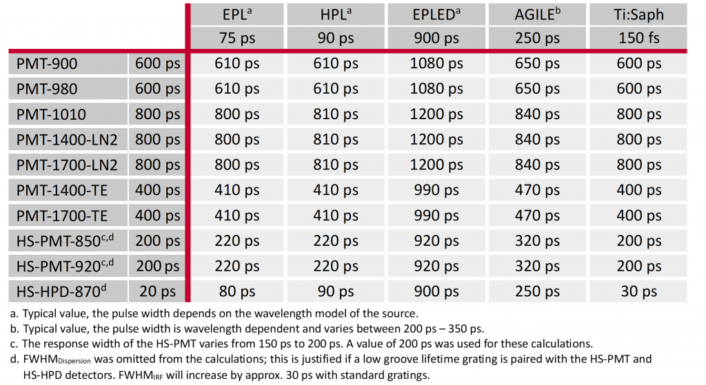
The source pulse widths, detector response widths and total FWHMIRF of the source and detector combinations that are possible in the FLS1000 are given in Table 1. The pulse widths of the sources are approximate as the exact pulse widths are dependent on the wavelength of the source.
Table 1: FWHMIRF of source and detector combinations in the FLS1000.

Minimum Lifetimes
Short lifetimes are calculated using reconvolution fitting. In reconvolution fitting, the IRF is measured experimentally and convoluted with the chosen decay model prior to fitting to take into account the width and shape of the IRF during the fitting routine. The width and shape of the IRF determines the minimum lifetime that can be reliably extracted using reconvolution fitting.
FWHMIRF / 10
One-tenth of the FWHMIRF is the most often quoted minimum lifetime achievable via reconvolution fitting. While technically possible, this minimum lifetime is achievable only under ideal experimental conditions. The sample must be a solution and the decay to be fitted must exhibit single exponential kinetics, and even under these conditions careful measurements are required to reach this limit. Multi-component exponential fits are not possible at this limit as they have too many degrees of freedom and solid samples have unpredictable scattering properties during the IRF acquisition for the one-tenth limit to be reliable.
FWHMIRF / 3
One-third of the FWHMIRF is a more practical estimate of the minimum lifetime that can be achieved via reconvolution fitting. Staying within this limit increases the fit reliability when measuring solutions with single exponential kinetics and enables solutions with multiexponential kinetics to also be fit. Analysis of decays of solid samples with single exponential kinetics is also possible within this limit. In general, when analysis of samples with complicated kinetics is expected; configure the FLS1000 to have as narrow a FWHMIRF as possible to increase the reliability of the fitting and reduce the experimental complexity of the measurements.
Conclusion
The width of the IRF is the key metric that determines the minimum measurable lifetime in the FLS1000. The FLS1000 can be equipped with a wide range of sources and detectors that enable IRF widths as low as 30 ps to be achieved. It is recommended to configure the FLS1000 sources and detectors with at least the FWHMIRF / 3 minimum lifetime limit in mind.


